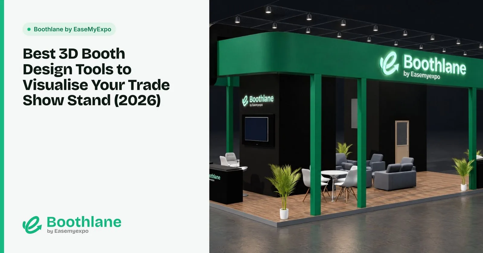
Exhibition Stall Working Drawings: What a Fabricator Needs Beyond the Render
Learn what exhibition stall working drawings should include, from plans and elevations to dimensions, materials, artwork and revision records for fabrication.
Contents
- At a glance
- How are working drawings different from renders?
- What can a working-drawing package contain?
- Which dimensions matter?
- How should the drawings relate to the 3D design?
- What must the organiser and fabricator still review?
- Where does Boothlane belong in the process?
- How can you prevent handoff confusion?
- Give the drawing package a usable index
- Frequently asked questions
- Can a fabricator build from a render alone?
- Is an OBJ or FBX file a working drawing?
- Who should prepare and check working drawings?
- Does a stall model automatically contain every drawing the fabricator needs?
- Make design intent easier to hand over
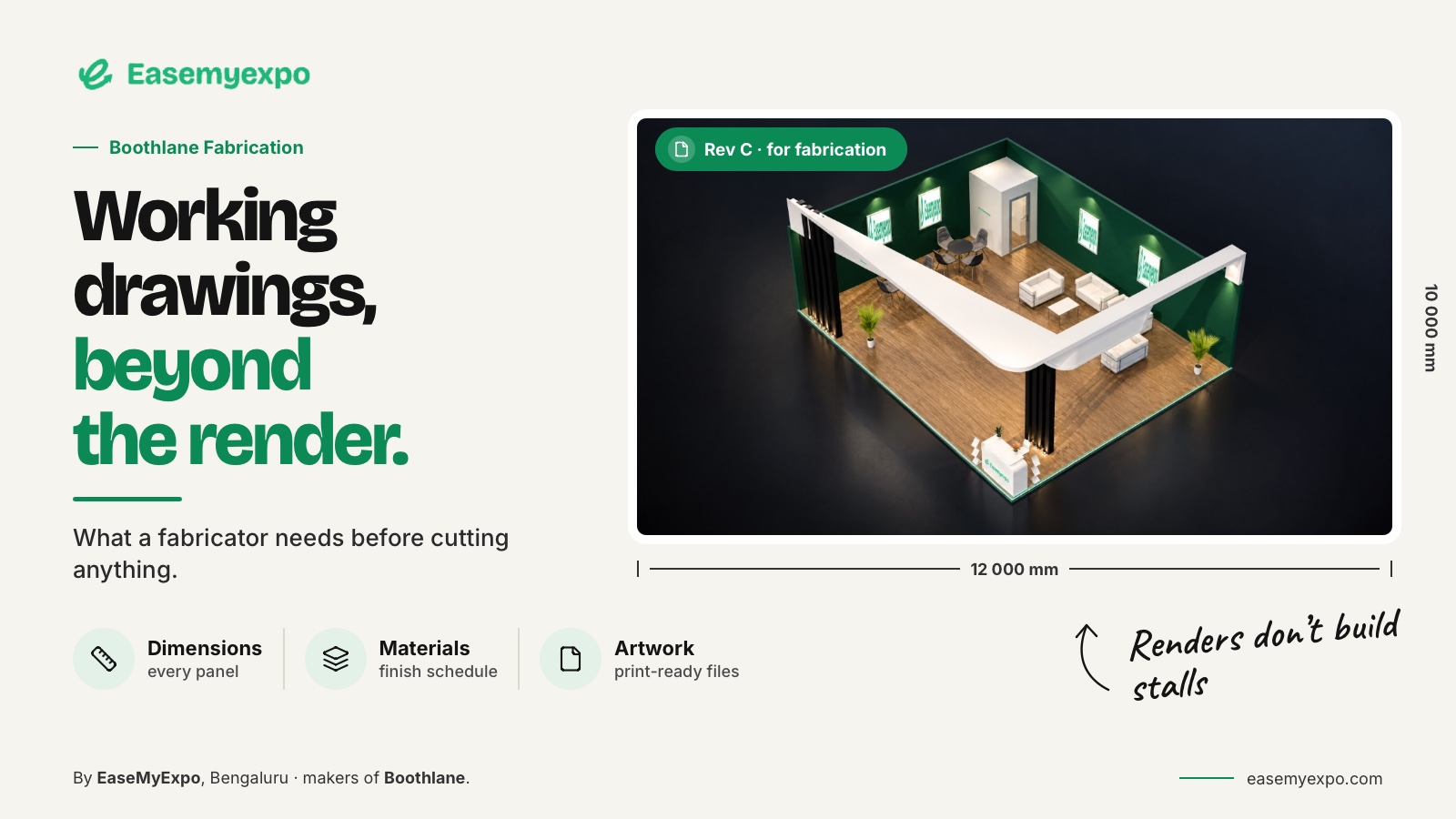
Exhibition stall working drawings communicate the measured and annotated information needed for a defined build task. A useful package can include plans, elevations, sections, details, material references and revision information. The exact requirements depend on the stand and event. A render or exported 3D model does not automatically replace this documentation or its technical review.
A client may approve the appearance of a booth long before every construction question is answered. Working drawings help make those remaining questions explicit.
At a glance
A render communicates appearance; working drawings explain what needs to be made. Define the required plans, elevations, details and schedules with the fabricator. Keep dimensions and revisions consistent, and separate visual approval from structural, electrical and organiser review.
How are working drawings different from renders?
A render explains appearance from a viewpoint. A drawing can communicate positions, dimensions, relationships and instructions that a perspective image leaves ambiguous. A section can explain an internal arrangement that the exterior view does not show.
An exported model may help the technical team, but it still needs the right interpretation and documentation. Do not assume a fabricator knows which dimension is controlling, which finish is final or whether a visual detail is decorative or structural.
SketchUp LayOut is an example of software specifically used to communicate models through drawing documents. The relevant lesson is the distinction between the model and the document package produced from it.
What can a working-drawing package contain?
Begin with the information the actual fabricator and organiser require. A floor plan may establish arrangement. Elevations may show heights and brand locations. Sections and details may resolve construction relationships. Material, lighting and artwork information may be supplied in linked schedules or separate documents.
A practical working-drawing package can include:
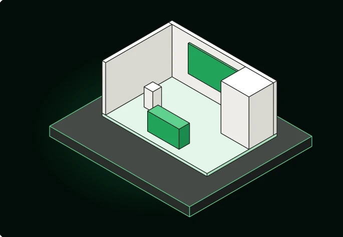
- Overall plan: Shows where the main stall elements are positioned.
- Elevations: Show intended heights, face arrangements and branding locations.
- Sections: Explain what happens inside or behind visible surfaces.
- Details: Resolve specific junctions, assemblies or construction relationships.
- Material references: Identify approved finishes or products.
- Artwork schedule: Shows which graphic belongs on each surface.
- Revision record: Identifies which information is current and what changed.
This is a scope guide, not an engineering specification or a claim that every stand needs the same set of sheets.
Which dimensions matter?
Identify dimensions that control the layout, product fit and interfaces with the booked space. Distinguish overall dimensions from local detail dimensions, and use a consistent unit system. The responsible technical team should resolve tolerances and construction allowances rather than inferring them from a render.
For an illustrative display counter, an overall size alone may not answer whether the client's product fits inside the opening. The document should communicate the dimension relevant to that task, not only the easiest dimension to annotate.
Avoid estimating a critical measurement from a perspective image. If the number is important, it needs a reliable source and an agreed place in the project record.
How should the drawings relate to the 3D design?
Use the same approved revision. When an object moves in the model, check every affected drawing and presentation. When technical development changes a visible part of the booth, return that change for the appropriate design approval.
Documentation-oriented software such as Vectorworks Spotlight describes design information and drawing outputs together. Whether your team uses that or another tool, the objective is consistency between representations rather than simply producing more files.
A small sheet index can help the team understand what has been issued and what is still pending. A missing document should not be disguised by a complete-looking folder.
What must the organiser and fabricator still review?
Work from the actual show's current requirements. Booth types, hall conditions, hanging elements and other restrictions can differ.
GES's event-specific rules illustrate this variation; they should not be copied as universal limits for another exhibition.
GES booth regulations and definitions
The responsible professionals must address the project's engineering, electrical and construction questions. This article does not provide structural design instructions or certify a booth for use. It explains the information flow that helps those decisions happen responsibly.
Record approval status clearly. “For discussion,” “for approval” and “issued for construction” should not be treated as interchangeable descriptions.
Where does Boothlane belong in the process?
EaseMyExpo helps users develop and present the editable stall design and supports documented OBJ/FBX model exchange. That model can inform the downstream technical workflow agreed with the designer and fabricator.
This guide does not claim that EaseMyExpo automatically generates a complete working-drawing or engineering package. Define the required documents separately and assign them to the people and tools responsible for producing them.
A clear boundary helps the whole team. The designer can use the visual model to explain intent while the technical team develops the information needed for the real build.
How can you prevent handoff confusion?
Issue a named package with a revision date, sheet list and brief description of the changes. Mark superseded files so they are not accidentally used. Keep unresolved items in an explicit log with an owner.
Ask the receiving team to review the package before fabrication is committed. A question answered at handoff is easier to manage than a hidden assumption discovered on site. Do not use a client's approval of a render as evidence that every construction detail has been accepted.
Give the drawing package a usable index
A hypothetical handoff could group sheets into overall layout, elevations, fascia details, product displays, graphics and services. Use the index to show which sheets are issued, which are awaiting information and which have been superseded.
The exact set depends on the build; these groups are examples, not a universal submission requirement.
Keep the same component names in the drawings, model and material schedule. A fabricator should not have to guess whether “Reception A” and “Front Counter” describe the same object.
When a detail changes, identify its effect on related sheets rather than sending an isolated replacement without context. This makes the package easier to check before purchasing or cutting materials.
Give each sheet a drawing number so workshop questions reference unambiguous information.
Frequently asked questions
Can a fabricator build from a render alone?
A render is a reference, not a complete technical instruction. The fabricator should identify and receive the measured and reviewed information needed for the project.
Is an OBJ or FBX file a working drawing?
No. It is a model-exchange file. It may support technical development, but the required drawings and annotations are separate deliverables.
Who should prepare and check working drawings?
Assign the task to people competent for the required technical scope, coordinated with the fabricator and organiser. Responsibility should be explicit in the project agreement.
Does a stall model automatically contain every drawing the fabricator needs?
No. Agree the required drawing scope separately. Boothlane supports the editable design and model exchange; the technical team still needs to prepare and review the relevant documents.
Make design intent easier to hand over
Use Boothlane to develop a clear stall model, then agree the technical package with the team responsible for turning it into a build.